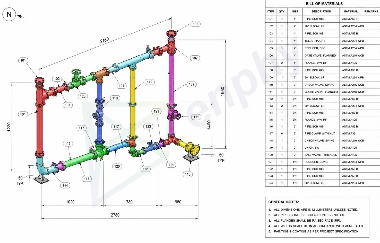
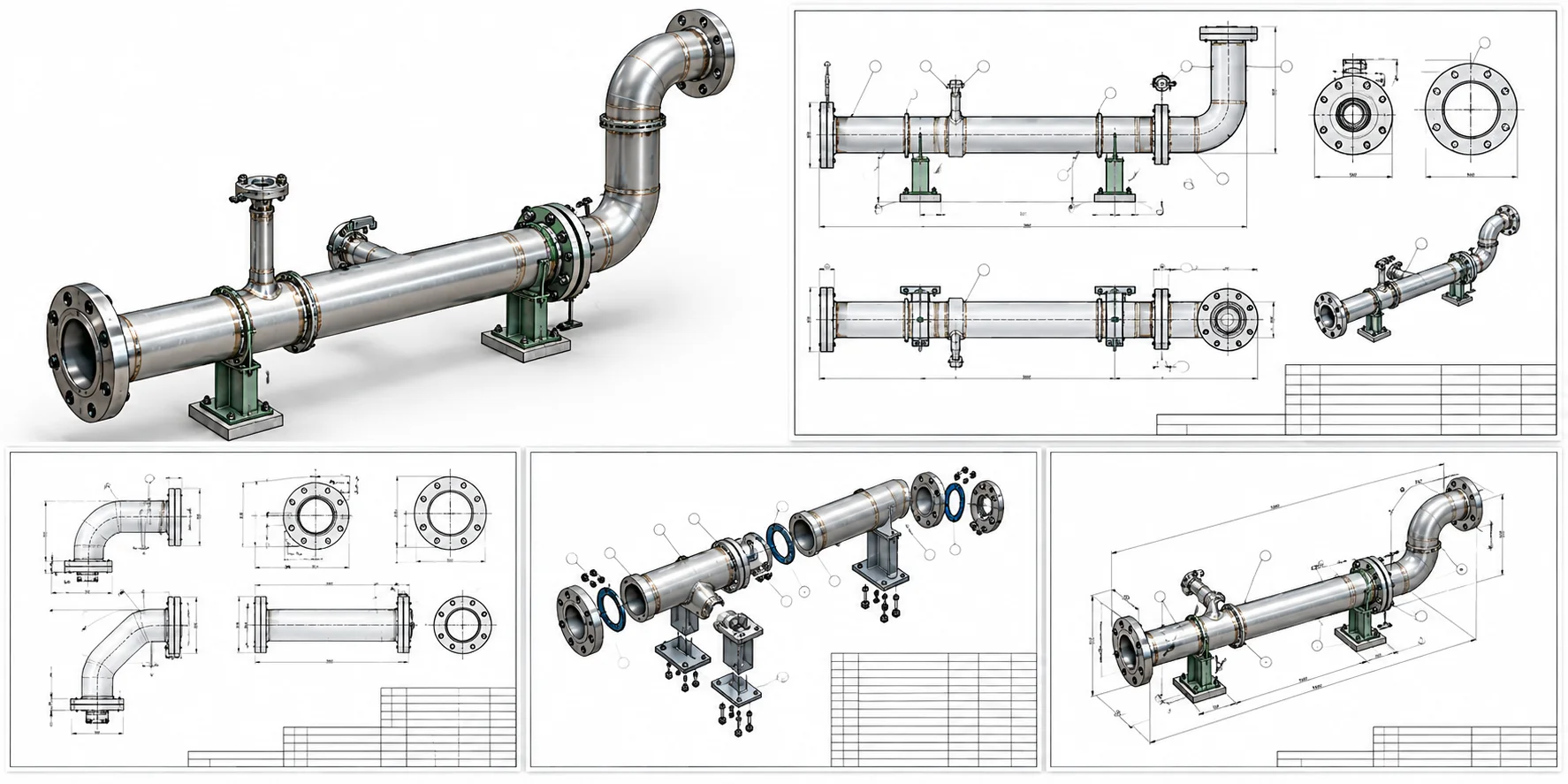
Piping spool drawing services for contractors and fabricators — detailed spool isometrics, weld maps,
BOMs and cut lists, developed around your fabrication standards and shop workflow.
A spool drawing has one job: to give the fabrication shop the information required to build the assembly accurately.
A pipe spool is a prefabricated section of piping consisting of pipe, fittings, flanges and other components assembled in the shop for delivery and installation in the field. The spool drawing is the instruction set that lets the shop build it — an isometric view of the assembly, a bill of materials, and the line data that ties it back to the design. On most shop floors it is simply called the spool sheet or the spool ticket.
Prefabrication moves more of the work into a controlled shop environment, where fit-up, welding, inspection and material handling can be planned before assemblies reach the field. Accurate spool drawings help the fabrication team identify what to cut, fit and weld while giving the field team clearly identified assemblies for installation.
The value depends on drawing accuracy. An incorrect dimension, fitting orientation or spool break can turn a prefabrication advantage into shop and field rework.
What a Spool Drawing Contains
Depending on the project and fabrication standard, a spool drawing typically includes a dimensioned isometric, spool and line identification, fitting and flange information, weld locations, flow direction, material information and an associated bill of materials. Additional information such as support references, test requirements and revision status can be included where required by the project.
Spool Drawings vs. Piping Isometrics
A piping isometric describes a complete line as designed. A spool drawing describes one buildable piece of it. The isometric answers what the system is; the spool drawing answers what goes on the truck. Getting from the complete piping line to individual spools requires decisions about spool breaks, fabrication constraints, transportation, access and field assembly.
Our Piping Spool Drawing Services
Our piping spool drawing services cover the detailing work between the design-intent documents and the fabrication shop. The scope on any given project is set by the fabrication requirements and the agreed project scope, and may include the following.
Modeling
Piping Model Development
A detailed piping model developed from design-intent documents, approved submittals and project specifications to the level required by the agreed fabrication scope.
Coordination
Multi-Trade Coordination
Where included in scope, the piping model is federated with the relevant architectural, structural and MEP models to identify routing, clearance and access conflicts before spooling begins.
Planning
Spool Break Planning
Break locations proposed around fabrication, transportation, rigging, access and installation constraints, with final break locations reviewed by the contractor or fabrication team before drawing issue.
Production
Spool Drawing Production
Bills of material, cut lists and weld maps organised by spool, in the structure the contractor’s fabrication workflow uses.
BOM & Data
Material & Fabrication Data
Bills of material, cut lists and weld maps organised by spool, in the structure the contractor’s fabrication workflow uses.
Assembly
Support & Assembly Info
Pipe support and hanger information, and prefabricated assembly organisation, where included in the agreed scope.
From Design Intent to Piping Spool Drawings
We develop the detailed piping model from the design-intent documents, approved submittals, project specifications and other available project information. The model is developed for coordination and fabrication detailing, coordinated with structure and other trades where required, and then used to produce the piping spool drawings.
Inputs We Can Start From
Piping design drawings
Architectural and structural drawings / models
Other trade models for coordination
P&IDs and line lists
Project specifications
Approved equipment submittals
Equipment schedules
Point-cloud data for existing conditions
Verified field dimensions and markups for retrofit work
Spool Break Planning
Spool breaks are developed around fabrication, transportation and installation constraints. Depending on the project, considerations may include available shop capacity, transport dimensions, lifting and rigging requirements, access openings, equipment connections, valve access and field-fit requirements.
We can propose spool breaks based on the agreed fabrication criteria, with final break locations reviewed and approved by the contractor or fabrication team before drawings are issued.
Proactive Spool Break Review
Break locations are optimized to reduce field welds, minimize transport risks, and match shop crane and truck bay capacities.
Piping Spool Drawing Deliverables
Piping Coordination Before Spooling
Fabrication Detailing and Quality Checks
Piping Spool Drawing Deliverables
Deliverables are defined by the fabrication requirements and agreed project scope. A typical package of piping spool fabrication drawings may include:
Deliverable
What It Includes
Spool isometric drawings
Dimensioned isometric views with line and spool identification, fitting information, weld locations, flange orientation and other fabrication details required by the project.
Bill of materials
Material information organized by spool, including size, description, quantity and other project-specific material references.
Cut list
Pipe cut lengths and associated information developed from the detailed piping model and fabrication requirements.
Weld map
Numbered weld locations with shop/field identification and additional weld information where required by the agreed fabrication workflow.
Spool map / key plan
Plan or model references showing where individual spools occur within the overall piping system to support identification and field installation.
Pipe support and hanger drawings
Support locations, types and attachment information where included in the agreed scope.
Output formats
PDF, DWG and other agreed model or data formats based on the contractor’s fabrication workflow.
Revisions can be clouded and revision-tagged in accordance with the project’s drawing standards, with issue and revision status maintained on the drawing package.
Piping Coordination Before Spooling
Spooling an uncoordinated model can simply carry unresolved clashes into fabrication. Where coordination is included in the scope, the piping model is federated with architectural, structural and other MEP models to identify routing and clearance conflicts before MEP spool drawings are produced.
Typical coordination conditions include structural penetrations, equipment connections, valve and strainer access, pipe supports, ceiling congestion and interfaces with ductwork, plumbing, fire protection and electrical systems.
Spatial conflicts that can be resolved through permitted routing or elevation adjustments are coordinated within the agreed design constraints. Conditions requiring a design or engineering decision are raised to the appropriate project stakeholder for clarification.
Fabrication Detailing and Quality Checks
Pipe spool fabrication drawings are developed from a piping model built to the level of detail required by the agreed fabrication scope. Where manufacturer-specific content or fabrication parts are available and required, they can be incorporated to represent actual fitting and equipment geometry.
Dimensions, fitting take-outs, flange orientation, bolt-hole requirements, weld gaps and other required fabrication information are developed around the contractor’s agreed fabrication standards and project requirements.
We detail from the contract documents, approved submittals, project specifications and applicable fabrication standards provided for the project. Enphy’s role is detailing and documentation. Engineering design, code determination and final engineering approval remain with the responsible design professional unless specifically included in the agreed scope.
Each drawing package goes through an internal QC review against the coordinated model, project inputs and agreed fabrication requirements before issue. Conditions that cannot be resolved from the available project information are raised for clarification rather than addressed through unapproved assumptions.
Software and Model Environments We Work In
Our piping detailing workflows support Revit, AutoCAD, Navisworks, Autodesk Construction Cloud, Fabrication CADmep and other project-specific fabrication environments where agreed. We confirm software versions, templates, content requirements and required output formats before production begins.
Revit MEP
Navisworks
AutoCAD
Autodesk Fabrication Suite
Bluebeam
DIALux
ElumTools
Piping Prefabrication and Modular Assemblies
Piping spool drawings can also support prefabricated risers, plant-room assemblies, pipe racks, skids and other modular piping assemblies where these form part of the project scope. The drawing package can be organized around the contractor’s preferred assembly, identification and installation sequence.
Piping Systems and Project Types
Commercial
Commercial HVAC Piping
Chilled water, heating hot water, condenser water, hydronic risers and plant-room piping, produced as MEP spool drawings where prefabrication is part of the project strategy.
Industrial
Industrial & Process Piping
Process lines, utilities, equipment connections, pipe racks and associated distribution piping.
Equipment
Equipment & Utility Piping
Piping around pumps, mechanical equipment and other building or process systems.
Distribution
Piping Risers & Distribution Systems
Vertical and horizontal piping distribution developed for coordination, prefabrication and installation.
Modular
Prefabricated Piping Assemblies
Plant rooms, racks, risers and other assemblies where prefabrication forms part of the project strategy.
Why Contractors Outsource Piping Spool Detailing
Piping fabrication workload does not always arrive in line with internal detailing capacity. Contractors and fabrication shops may need external piping detailing support when multiple projects move into coordination, prefabrication or fabrication at the same time, or when a large package temporarily exceeds internal production capacity.
Enphy can work as an extension of your internal BIM/VDC or detailing team, taking on defined spool packages or project scopes while working within your existing standards and coordination process.
Flexible Capacity
— Add detailing resources during peak project workloads.
Defined Scope
— Assign a line, system, level, area or complete project package.
Your Standards
— Developed around your agreed templates, numbering and annotation.
Project Communication
— Drawing status and revisions managed through agreed workflow.
How We Work With Your Team
We begin by reviewing the project scope, available model or drawings, fabrication standards and required deliverables. For new clients or unfamiliar fabrication workflows, a defined pilot package can be useful for aligning templates, spool numbering, annotation, BOM structure and revision standards before full production begins.
Once the workflow is agreed, the project is managed against the required drawing schedule, coordination milestones and revision cycle.
Turnaround depends on factors such as model maturity, number and complexity of piping systems, project size, fabrication requirements and revision activity. The project schedule is established after reviewing the actual scope rather than applying a blanket turnaround time.
A piping spool drawing is a shop drawing for one prefabricated section of pipe. It shows the assembly as a dimensioned isometric, with weld locations and types, fitting and flange orientation, a bill of materials and the line data from the design. It provides the fabrication shop with the information required to cut, fit, weld and assemble the spool.
What is the difference between a piping isometric and a spool drawing?
An isometric describes a complete piping line as designed. A spool drawing describes one buildable, shippable piece of that line. A complete piping line may be divided into multiple spools, with break locations developed around fabrication, transportation, rigging, access and field-installation requirements.
What is included in your spool drawing package?
A typical spool drawing package may include spool isometrics, bills of materials, cut lists, weld maps, spool maps or key plans, and pipe support or hanger information where included in the agreed scope. Typical drawing deliverables include PDF and DWG, with other formats agreed based on the project workflow.
Do you decide the spool breaks, or do we?
We can propose spool breaks based on the agreed fabrication, transportation and installation criteria. Final break locations are reviewed and approved by the contractor or fabrication team before the spool drawings are issued.
Can you work from a design-intent model, or do you need a fabrication-level model?
Yes. We develop the detailed piping model from design-intent documents, approved submittals, project specifications and other available project information. Where required, the model is coordinated with structure and other trades before the spool drawings are developed.
Which software and file formats do you deliver in?
Typical drawing deliverables include PDF and DWG. Model and fabrication-data formats depend on the software environment, project requirements and agreed scope.
Send Us Your Piping Drawings
Have an upcoming piping fabrication or spool drawing requirement? Send us the available drawings, specifications and required deliverables. We’ll review the scope and provide a project-specific quote.